Flange facing is a critical machining operation in industrial piping systems that ensures proper sealing between flanged connections. Whether you’re maintaining power generation equipment, repairing petrochemical facilities, or working on shipbuilding projects, understanding flange facing fundamentals and having the right equipment can make the difference between a reliable seal and a costly leak.
What Is Flange Facing?
Flange facing refers to the machining process of preparing or reconditioning the gasket seating surface of a pipe flange. This surface, known as the flange face, serves as the contact area where gaskets seat to create a leak-tight seal between two flanged connections. Over time, flange faces can become damaged, corroded, or worn, compromising their ability to maintain proper sealing pressure and leading to potential leaks or system failures.
The flange facing process involves machining the gasket surface to restore it to like-new condition, ensuring it meets the required surface finish specifications and provides uniform contact with the gasket material. This restoration is essential for maintaining the integrity of piping systems in industries where reliable sealing is critical for safety, environmental compliance, and operational efficiency.
Common Flange Face Types
Understanding the different flange face types is essential for selecting appropriate gaskets and machining techniques. ASME B16.5 and B16.47 define several standard flange facings, each designed for specific applications and pressure requirements.
Raised Face (RF)
The raised face flange is the most prevalent type in process plant applications. As the name suggests, the gasket surface is raised above the bolting circle face, concentrating pressure on a smaller gasket area to increase the pressure containment capability of the joint. The raised section allows for use of various gasket designs, including flat ring sheet types and metallic composites such as spiral wound and double jacketed gaskets.
For pressure classes 150 and 300, the raised face height measures approximately 1.6 mm (1/16 inch). In higher pressure classes 400, 600, 900, 1500, and 2500, the raised face height increases to approximately 6.4 mm (1/4 inch) to handle greater pressure loads. The standard surface finish for ASME B16.5 RF flanges ranges from 125 to 250 microinches Ra (3 to 6 micrometers Ra), creating concentric serrations that help grip and seal the gasket.
Flat Face (FF)
Flat face flanges have a gasket surface that sits in the same plane as the bolting circle face, with no raised section. These flanges are commonly found in applications involving cast iron components, such as valve bodies or pump casings, where the mating flange or fitting is manufactured from casting.
It’s critical to note that flat face flanges should never be bolted directly to raised face flanges. According to ASME B31.1, when connecting flat face cast iron flanges to carbon steel flanges, the raised face must be removed from the carbon steel flange, and a full face gasket must be used. This requirement prevents the thin, brittle cast iron flange from being stressed by the gap created by the raised face, which could lead to flange cracking or failure.
Ring Type Joint (RTJ)
Ring type joint flanges feature a machined groove that accommodates a metal ring gasket, typically made from soft iron, stainless steel, or other alloys. The ring gasket sits in matching concentric or octagonal grooves machined into both mating flange faces. When the bolts are tightened, the metal ring deforms slightly, creating a metal-to-metal seal.
RTJ flanges excel in high-pressure, high-temperature applications where standard gasket materials may fail. The metal ring gasket provides superior sealing capability and can withstand extreme operating conditions common in oil and gas production, refining, and chemical processing. RTJ connections require precise groove dimensions and surface finishes to achieve proper sealing.
Tongue and Groove (T&G)
Tongue and groove flanges feature matching machined profiles where one flange has a raised ring (the tongue) and the mating flange has a corresponding recessed groove. Unlike male and female facings, the tongue and groove design does not extend into the flange base, which helps retain the gasket on both its inner and outer diameters.
This design offers several advantages, including self-alignment during assembly and the ability to act as a reservoir for gasket adhesives when used. Tongue and groove joints are commonly found on pump covers, valve bonnets, and heat exchanger components where precise alignment and reliable sealing are essential.
Male and Female (M&F)
Male and female flange faces must be used as matched pairs. The male face features an area that extends beyond the normal flange face, while the female face has a matching depression machined into its surface. The female face is typically 3/16 inch deep, while the male face extends 1/4 inch high, with both surfaces smooth finished.
The outer diameter of the female face serves to locate and retain the gasket during assembly. Male and female facings are available in both large and small configurations and are commonly found on heat exchanger shell-to-channel and cover flanges. Custom male and female facings can be specified for specialized applications requiring enhanced sealing performance.
Why Flange Facing Matters
Proper flange facing directly impacts system reliability, safety, and maintenance costs across industrial operations. A well-machined flange face ensures uniform gasket compression, which is essential for creating and maintaining a leak-tight seal under varying pressure and temperature conditions.
Preventing Leaks and Failures
Damaged, corroded, or improperly finished flange faces create uneven contact pressure across the gasket surface. This leads to stress concentrations that can cause gasket failure, resulting in leaks of process fluids, steam, or hazardous materials. In power generation facilities, even minor steam leaks from boiler flanges reduce efficiency and create safety hazards. In petrochemical plants, leaks can result in environmental violations, production shutdowns, and safety incidents.
Meeting Industry Standards
Industry standards like ASME B16.5 specify precise surface finish requirements for flange faces to ensure consistent sealing performance. The typical phonographic finish, characterized by concentric serrations, provides an ideal surface for gasket seating. These serrations help grip the gasket material while allowing for slight irregularities in the gasket surface, creating a more forgiving seal that accommodates minor variations in bolt load or thermal expansion.
Reducing Maintenance Costs
Reconditioning worn flange faces on-site eliminates the need to remove entire piping sections or replace flanges, significantly reducing maintenance time and costs. During planned outages at power plants or refineries, the ability to quickly resurface flanges in place keeps projects on schedule and avoids expensive downtime extensions. This is particularly important during spring boiler outages when every day of downtime represents significant lost revenue.
Extending Equipment Life
Regular flange facing maintenance as part of predictive or preventive maintenance programs extends the service life of piping systems and connected equipment. Rather than replacing entire flanged assemblies when gasket surfaces become damaged, reconditioning allows continued use of existing piping infrastructure at a fraction of the replacement cost.
The Flange Facing Process
Effective flange facing requires the right combination of technique, equipment, and attention to detail. Whether performed in a fabrication shop or on-site during maintenance outages, the process follows a systematic approach to achieve the required surface finish and dimensional accuracy.
Surface Preparation
Before machining begins, the flange face must be cleaned of any remaining gasket material, rust, scale, or other contaminants. This ensures accurate measurement of the existing surface condition and prevents damage to cutting tools. Wire brushing or scraping removes loose material, while chemical cleaners can dissolve stubborn gasket residues.
Equipment Setup
Proper mounting and alignment of the flange facing machine is critical for achieving accurate results. Internal diameter (ID) clamping machines, like the FLANGE HOG® 110, mount directly to the pipe or flange bore using precision clamping systems. The clamping mechanism must distribute holding force evenly to prevent the workpiece from shifting during machining.
For machines with multiple clamping positions, selecting the correct clamp pads and extensions ensures the tool fits securely within the ID range of the flange being machined. External or OD-mounted machines use different clamping strategies but require the same attention to secure mounting and proper alignment.
Feed and Cutting
The cutting tool is positioned to contact the flange face and fed gradually across the surface to remove material. Feed rates must be controlled to achieve the desired surface finish while avoiding chatter, excessive tool wear, or workpiece damage. Manual machines use hand-operated feed mechanisms that give operators tactile feedback, while powered machines may incorporate adjustable feed rates for different materials and cutting conditions.
Multiple passes may be necessary to remove deep scoring or corrosion, with increasingly finer cuts used to achieve the final surface finish. The depth of cut on each pass depends on the material being machined, the condition of the flange face, and the capabilities of the cutting tool.
Achieving the Proper Finish
ASME B16.5 specifies surface finish requirements measured in microinches Ra (roughness average). For raised face flanges in most applications, the target finish ranges from 125 to 250 microinches Ra. This finish creates the characteristic phonographic pattern of concentric serrations that optimize gasket sealing.
The cutting tool geometry, feed rate, and rotational speed of the machine all influence the final surface finish. Sharp cutting tools in good condition produce cleaner finishes with less effort. Proper coolant or cutting fluid application can improve finish quality and extend tool life, though many field applications perform dry machining for simplicity.
Inspection and Verification
After machining, the flange face should be inspected to verify it meets dimensional and finish requirements. Visual inspection identifies obvious defects like torn metal, chatter marks, or incomplete machining. Surface finish can be measured using profilometers or compared to standard surface finish samples. Dimensional checks verify that the raised face height and diameter match specifications.
Flange Facing Equipment Solutions
Selecting the right flange facing equipment depends on the size range of flanges you work with, the location where work will be performed (shop versus field), and the frequency of use. Esco Tool offers specialized solutions for different applications and requirements.
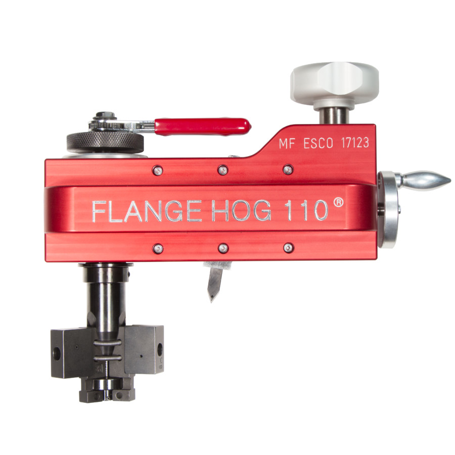
FLANGE HOG® 110: Portable Hand-Operated Flange Facer
The FLANGE HOG® 110 delivers professional flange facing results without requiring electrical, hydraulic, or air power sources. This manually operated tool is ideal for field service technicians, maintenance crews, and fabrication shops that need portable equipment capable of handling a wide range of flange sizes.
The FLANGE HOG® 110 handles flanges from 0.9 inches to 10.3 inches ID with machining capability up to 14 inches OD. This range covers the majority of common piping flanges found in industrial facilities, from small process piping to larger steam and water lines. The proprietary clamping system mounts quickly to the flange ID with consistent accuracy, eliminating the setup complexity and alignment issues common with other mounting methods.
A worm gear mechanism provides smooth swing operation that produces a precise phonographic finish meeting ASME B16.5 standards for both raised face (RF) and flat face (FF) applications. The hand-operated feed gives operators complete control over cutting depth and surface finish quality. Different feed settings accommodate both smooth finishing and stock removal operations.
Double-sided cutting inserts are specially formed to cut through carbon steel, stainless steel, alloyed steel, aluminum, and cast iron. Each cutting edge provides long service life, and when one edge dulls, operators simply flip the insert to use the fresh edge. The insert holder offers both neutral (straight) and 90-degree positions for different machining requirements.
Each FLANGE HOG® 110 kit arrives ready to use in a sturdy carrying case that organizes all components for quick access. The complete kit includes the housing assembly, feed mechanism, tool post, cutting inserts, clamping components (mandrel, wedges, clamp pads, clamp ribs, actuator, and spring), and the clamp release wrench. At just 15.4 pounds (7 kg), the entire system is genuinely portable for one-person operation.
When to Choose Manual vs. Powered Equipment
Hand-operated tools like the FLANGE HOG® 110 excel in situations where portability and simplicity outweigh production speed. Field service applications, remote locations without power access, and occasional flange facing needs are ideal applications for manual equipment. The elimination of power requirements, hoses, and compressors reduces setup time and complexity while improving reliability.
Powered flange facing machines offer faster material removal and reduced operator fatigue for high-volume shops or frequent large-diameter work. These machines use pneumatic, hydraulic, or electric motors to rotate the cutting head while operators control feed rates. The increased cutting speed comes at the cost of greater equipment complexity, higher initial investment, and power supply requirements.
For many industrial maintenance operations, having both manual and powered options available provides flexibility to match equipment capabilities to specific job requirements. Critical path work during outages may benefit from powered equipment’s speed, while routine maintenance and field service applications may be better served by manual tools’ simplicity and portability.
Applications Across Industries
Flange facing serves critical functions across numerous industrial sectors, each with specific requirements and challenges.
Power Generation
Power plants rely on hundreds or thousands of flanged connections in boiler systems, steam piping, feedwater systems, and cooling circuits. During scheduled outages, maintenance crews must inspect and recondition flange faces to ensure reliable sealing when the plant returns to service. The ability to resurface flanges quickly in place keeps outage schedules on track and prevents costly delays.
Boiler tube panel connections, economizer flanges, and superheater joints operate under extreme temperature and pressure conditions that accelerate gasket seat wear. Regular flange facing maintenance during outages extends the service life of these connections and reduces the risk of leaks that could force unplanned shutdowns.
Petrochemical and Refining
Chemical processing and refining facilities contain extensive piping networks handling corrosive, high-temperature, and high-pressure fluids. Flange face degradation from chemical attack or thermal cycling can compromise sealing integrity, leading to product loss, environmental releases, or safety incidents. On-site flange facing capabilities allow maintenance teams to address problems immediately rather than waiting for replacement parts or shop services.
Heat exchanger flanges require particular attention in these applications, as leaks between process and cooling circuits can contaminate products or create unsafe conditions. The ability to recondition male and female flange faces in place reduces downtime and maintains production schedules.
Marine and Shipbuilding
Shipboard piping systems face unique challenges from corrosive seawater, constant vibration, and space constraints that make maintenance difficult. Flange facing equipment that operates in confined spaces with manual power provides shipyard maintenance crews the flexibility to work in engine rooms, pump rooms, and other tight locations.
Naval vessels and commercial ships require absolute reliability from piping systems that transport fuel, lubricating oil, steam, and seawater. Regular flange maintenance during scheduled yard periods prevents in-service failures that could compromise vessel operations or safety.
Industrial Manufacturing
Manufacturing facilities across industries rely on utility systems (steam, compressed air, cooling water) and process piping that utilize flanged connections. Maintenance departments need cost-effective solutions for addressing flange leaks without extended production interruptions. Portable flange facing tools enable quick repairs during scheduled maintenance windows or off-shift periods.
Best Practices for Flange Facing
Achieving consistently excellent results requires attention to several key practices beyond simply operating the equipment.
Safety First
Always follow proper lockout/tagout procedures when working on piping systems. Verify that lines are depressurized, drained, and isolated before beginning work. Wear appropriate personal protective equipment including safety glasses, gloves, and hearing protection when operating flange facing equipment.
Material Considerations
Different materials machine differently and may require adjustments to feed rates, cutting speeds, or tool selection. Stainless steels and high-alloy materials work-harden more readily than carbon steel, requiring sharper tools and more conservative cutting parameters. Cast iron is brittle and prone to chipping, demanding light cuts and sharp tools to avoid tearing the surface.
Tool Maintenance
Keep cutting tools sharp and properly aligned for best results. Dull tools require excessive force, produce poor surface finishes, and increase the risk of chatter or workpiece damage. Inspect cutting inserts regularly and replace them at the first signs of wear or chipping. Clean and lubricate moving parts of the facing machine according to manufacturer recommendations to ensure smooth operation and long service life.
Documentation
Maintain records of flange facing work performed, including flange identification, date of service, surface finish achieved, and any observations about flange condition. This documentation supports predictive maintenance programs and helps identify problem flanges that may require more frequent attention or eventual replacement.
Conclusion
Flange facing is an essential maintenance skill and capability for industrial facilities that depend on reliable piping systems. Understanding the different flange face types, proper machining techniques, and available equipment options enables maintenance teams to address sealing problems quickly and cost-effectively.
The FLANGE HOG® 110 represents a practical solution for field service and maintenance applications where portability, simplicity, and reliability matter most. Its ability to recondition flanges from small process piping to larger utility lines without external power makes it an invaluable tool for power generation facilities, petrochemical plants, shipyards, and manufacturing operations.
Whether you’re planning for spring outage season, building your maintenance tool inventory, or addressing an immediate sealing problem, having the right flange facing equipment available ensures you can maintain system integrity without costly delays or shutdowns. Contact Esco Tool to learn more about flange facing solutions for your specific application or to arrange equipment rental for your next outage or project.
Related Content